Introduction
The power level of a system or a signal chain is one of the main indicators to guarantee a reliably signal integrity with a sufficient signal-to noise-ratio.
In a signal chain each device is dependent that the previous one delivers the proper signal level. If the level is too high nonlinear performance will occur or in the worst case equipment will be damaged. Is the level to low, the carrier signal can be lost in the noise.
In DC applications or even at low frequencies voltage and current measurements are performed to calculate the power. Because of effects like a standing wave, were the voltage and current varies along a cable, this kind of measurements are not suitable to get reliable results. Despite these effects the power stays always constant and is therefore a much useful quantity for judging high frequencies transmission lines.
Units
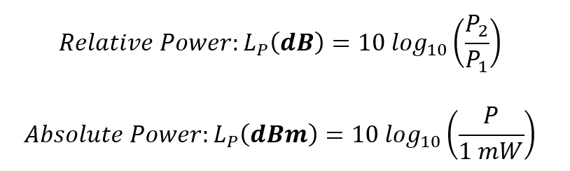
To deal with very big and very small power levels at the same time a logarithmic scale is used. A dB is the logarithm of a ratio of two power levels, so it describes the relative power to compare two levels. To get an absolute value a reference of 1 mW is assigned. The result is the dBm, or dB relative to 1 mW.
How to Measure
Because in modern applications signals are not only modulated in their frequency but also in their amplitude and other specifics (even pulsed signals are widespread) a momentary measurement of power is difficult and often not a useful information. Therefore, the average power of a signal is usually measured.
The power level of a signal can be measured by a variety of different instruments. Both a Spectrum Analyzer and a Network Analyzer can be used to perform a power measurement. It is necessary to keep in mind, that these devices work frequency selective. The spectrum analyzer can only perform power measurements in the configured bandwidth. An RF power meter measures the power of the entire frequency range including all carrier waves, all harmonics and intermodulation products.
To perform these measurements over a wide band specific sensors are used. The most common type today is the diode detector. The detector basically consists of a line termination with the corresponding impedance to the system. A diode is used to rectify the signal and a bypass capacitor is used to remove any HF signal getting through the diode. The rectified signal can now be picked up by an Analog to Digital converter.
Implementation
Most of DEV’s products have a built-in RF-sensing functionality that measures the accumulated RF power over the entire bandwidth. This value is a quality indicator to either send an alarm to an M&C System or to perform a redundancy switching fully autonomously. This feature is realized by coupling out the signal from the main transmission path and feeding it to a built-in RF power detector IC. This chip is based on the same principle as the diode detector. The coupler and sensor are tuned for the respective frequency band to guarantee a measurement over the whole spectrum in use.
Because power measurement in optical transmission lines is even more challenging, it is always realized on the electrical side of the Optribution products. For example, on a generic optical transmission card the incoming signal is sensed and on reception cards the out bounding ones are detected. This moves the measurement to the electrical section of the signal flow, making it much easier to perform the measurement.
Of course, unfortunately a small IC cannot replace special instruments like a spectrum analyzer. The measured values must therefore be interpreted as an indicator for the condition of the transmission line and not as an exact measured value.
Implications for adjusting the threshold level
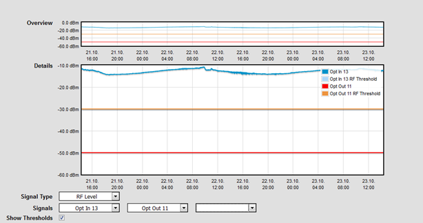
Within DEV devices, a threshold level is set for every channel. If the threshold level is undershot, a field, or an LED turns red. At the same time, either an alarm is triggered or an automatic switch to a backup signal is performed. In practice, it has been useful to set the threshold level right in the middle of the signal level when a signal is applied and the signal level when a signal fails, to ensure reliable switching and monitoring.
Important to remember
- The power in RF application is usually measured directly and over a certain amount of time.
- dBm uses a logarithmic scale and is relative to 1 mW
- A spectrum analyzer and a network analyzer measure the power over a narrow frequency band section. Power meters and the ICs in DEV products measure a wide frequency band section. Depending on the exact bandwidth these devices use for the measurement, each of them can give different results for the same signal.
- In the Optribution product line, the electrical power is measured, not the optical one, as the measurement of an electrical signal is easier to perform and the electrical signal level is perfectly adequate for the purposes needed.
About DEV Systemtechnik: DEV Systemtechnik develops and manufactures a complete range of products and systems for the optical and electrical transmission of Radio Frequency (RF) signals via coaxial cable or fiber. For over 20 years DEV has designed, engineered, and manufactured RF transmission equipment for satellite, broadcast, and cable applications. All products are built to meet the highest standards of system availability, reliability and manageability.
More Information? Please contact:
DEV Systemtechnik GmbH
Email: info@dev-systemtechnik.com
Phone: +49 (0) 6031/ 6975-100
Fax: +49 (0) 6031/ 6975-114